


TECHNICAL DETAILS & DIMENSIONS


Couplings and Fluid Drives - Type A

coupling type |
|
A00 |
A0 |
A1 |
A2 |
A3 |
A3B |
A4 |
A4B |
A45 |
A5 |
A5B |
A55 |
A6 |
A7 |
A8 |
A9 |
A10 |
A11 |
Style STD |
Maximum KW per 1000 |
2.55 |
6 |
11 |
30 |
60 |
60 |
120 |
120 |
212 |
303 |
303 |
358 |
485 |
966 |
1815 |
3023 |
4845 |
5895 |
Insert |
Max. Cont. Torque Nm |
24.2 |
56.9 |
107 |
286 |
569 |
569 |
1139 |
1139 |
2014 |
2876 |
2876 |
3400 |
4598 |
9168 |
17 225 |
28684 |
45981 |
55945 |
|
|
|
|
|
|
|
|
|
|
|
|
|
|
|
|
|
|
|
|
|
Style HD |
Maximum KW per 1000 |
- |
-- |
15 |
40 |
78 |
78 |
163 |
163 |
275 |
398 |
398 |
475 |
658 |
1170 |
2205 |
3510 |
5663 |
7920 |
Insert |
Max. Cent. Torque Nm |
- |
- |
142 |
337 |
740 |
740 |
1545 |
1545 |
2605 |
3772 |
3772 |
4500 |
6242 |
11104 |
20 926 |
33 311 |
53739 |
75163 |
|
|
|
|
|
|
|
|
|
|
|
|
|
|
|
|
|
|
|
|
|
Technical |
Max. Speed-Unbal |
9100 |
8200 |
7250 |
5440 |
4200 |
4200 |
3275 |
3275 |
2800 |
2600 |
2600 |
2350 |
2200 |
1900 |
1600 |
1350 |
1100 |
1100 |
Data |
Max. Speed-Bal. |
10 000 |
9000 |
8000 |
6500 |
4800 |
4800 |
3600 |
3600 |
3100 |
2900 |
2900 |
2600 |
2500 |
2200 |
1850 |
1600 |
1250 |
1250 |
|
|
Moment of Inertia (Kg-m2) |
- |
- |
0.012 |
0.005 |
0.01 |
0.02 |
0.05 |
0.075 |
0.1 |
0.155 |
0.21 |
0.275 |
0.437 |
0.825 |
2.326 |
4.95 |
12 |
16 |
|
|
Weight (Kg) |
0.2 |
1 |
1.8 |
3.8 |
6.2 |
8.5 |
12.5 |
16 |
19 |
26 |
31 |
36 |
47 |
75 |
137 |
218 |
350 |
410 |
|
|
|
|
|
|
|
|
|
|
|
|
|
|
|
|
|
|
|
|
|
Displacement |
Axial Tolerance |
+0.3 |
+0.3 |
+0.5 |
+0.5 |
+0.7 |
+0.7 |
+0.8 |
+0.8 |
+1.0. |
+1.0. |
+1.0. |
+1.0. |
+1.0. |
+1.0. |
+1.5 |
+1.5 |
+2.0 |
+2.0 |
Values |
Radial/Parallel |
0.20 |
0.30 |
0.30 |
0.50 |
0.50 |
0.50 |
0.70 |
0.70 |
0.70 |
0.70 |
0.70 |
0.80 |
0.80 |
1.00 |
1.00 |
1.00 |
1.50 |
1.50 |
|
|
Angular Tolerance |
2 |
2 |
2 |
2 |
2 |
2 |
1.3 |
1.3 |
1.3 |
1.3 |
1.3 |
1.3 |
1.3 |
1 |
1 |
1 |
1 |
1 |
|
|
|
|
|
|
|
|
|
|
|
|
|
|
|
|
|
|
|
|
|
|
|
coupling type |
A00 |
A0 |
A1 |
A2 |
A3 |
A3B |
A4 |
A4B |
A45 |
A5 |
A5B |
A55 |
A6 |
A7 |
A8 |
A9 |
A10 |
A11 |
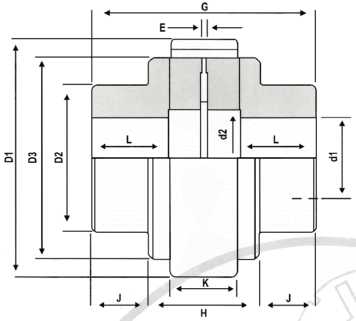
Dimensions |
Max Bore d1 |
22.2 |
34.9 |
41.3 |
53.97 |
54.0 |
69.8 |
70 |
95.2 |
82.5 |
85 |
114.3 |
101.6 |
114.3 |
139.7 |
150 |
180 |
210 |
210 |
(mm) |
Pilot Bore |
4 |
8 |
14 |
17 |
19.0 |
19 |
24 |
24 |
25 |
29 |
29 |
30 |
39 |
48 |
63 |
73 |
96 |
96 |
|
|
|
|
|
|
|
|
|
|
|
|
|
|
|
|
|
|
|
|
|
|
|
D1 |
44 |
65 |
83 |
111 |
144 |
144 |
182 |
182 |
202 |
225 |
225 |
250 |
265 |
306 |
363 |
42.5 |
523 |
503 |
|
|
D2 |
35 |
52 |
65 |
80 |
85.0 |
105 |
110 |
140 |
125 |
140 |
160 |
155 |
180 |
205 |
242 |
280 |
330 |
350 |
|
|
D3 |
35 |
52 |
65 |
86 |
116 |
116 |
150 |
150 |
170 |
190 |
190 |
215 |
233 |
267 |
326 |
385 |
483 |
458 |
|
|
d2 |
22 |
32 |
39 |
45 |
52.0 |
52 |
70 |
70 |
90 |
89 |
89 |
115 |
112 |
135 |
157 |
188 |
218 |
216 |
|
|
G |
51 |
73 |
91 |
127 |
156 |
156 |
180 |
180 |
198 |
216 |
216 |
246 |
260 |
310 |
382 |
420 |
482 |
512 |
|
|
L |
19 |
28 |
34 |
47 |
56.0 |
56 |
63 |
63 |
70 |
77 |
77 |
90 |
95 |
116 |
147 |
162 |
188 |
190 |
|
|
Standard "DBSE" |
13 |
17 |
23 |
33 |
44.0 |
44 |
54 |
54 |
58 |
62 |
62 |
66 |
0.7 |
78 |
88 |
95 |
106 |
132 |
|
|
Dist. Between Hubs 'E" |
1.5 |
1.5 |
1.5 |
2.5 |
2.5 |
2.5 |
3.5 |
3.5 |
3.5 |
3.5 |
3.5 |
3.5 |
3.5 |
4 |
5 |
5 |
6 |
6 |
|
|
H |
- |
- |
- |
55 |
6.5 |
65 |
85 |
85 |
93 |
101 |
101 |
109 |
119 |
134 |
154 |
162 |
192 |
216 |
|
|
J |
- |
- |
- |
36 |
45.0 |
45 |
47 |
47 |
52 |
57 |
57 |
68 |
70 |
88 |
114 |
129 |
145 |
148 |
|
|
K |
12 |
16 |
22 |
32 |
42.0 |
42 |
51 |
51 |
56 |
59 |
59 |
64 |
67 |
75 |
85 |
92 |
102 |
128 |
1) STD inserts will be supplied as standard unless specified. High Torque (HD) inserts can be supplied upon request
2) Maximum speed are based on Casiron Hubs. Higher speeds can be obtained using Ductile Iron or Steel Hubs – Consult Autogard
3) Distance between shafts ends (DBSE) is based on the shafts mating flush with the end of the hub face. Short or longer shaft separations may be obtained by overhanging the shaft
4) Weights & Intertias are based on solid hubs.