Copyright © All rights reserved. Made By RT World of Business.


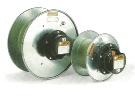
The concept of the reels is to provide a modular system that retains all the quality and reliability of a standard spring driven cable reel . In this case the modular design allows for easy storage and thanks to the innovative design of the reels, replacing just one part is extremely easy.
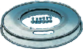
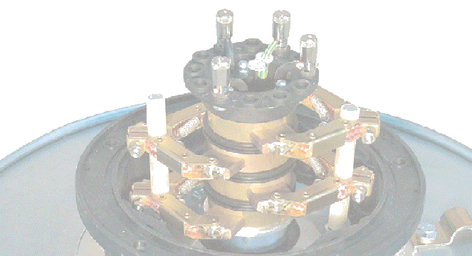
Side Plates
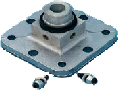
Mounting Flange
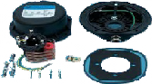
Slipring Collector
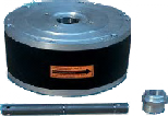
Spring Body

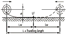
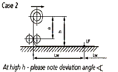
Case 1 & 2
Horizontal mobile application
The cable is unreeled on a flat and continuous surface. The cable is unreeled horizontally in either travelling directions.

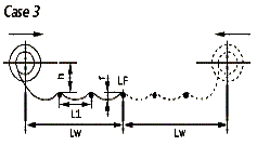
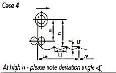
Case 3 & 4
Horizontal mobile application
The cable is reeled out on supports
(L1 < 1 m) or on rollers or rounded smooth supports L1 = 1 to 3 m, depending on the cable size) The cable is unreeled horizontally in either travelling directions.
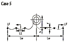
Case 5
Stationary application
The cable is unreeled horizontally in either travelling directions through support rollers (L1 =1 to 3 m, depending on the cable size). This tape of application is not recommended
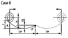
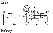
Case 6 & 7
Horizontal mobile application
The cable is unreeled horizontally, above the ground and without support, in either traveling directions. The catenerary f1 must be calculated accurately. As a rule the value of fmax is approximately 10% of L.
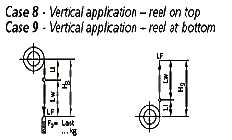
Case 8 & 9
Vertical application
The cable is unreeled vertically downwards (downward inclination) Alternatively the cable is unreeled vertically upwards (upward inclination).
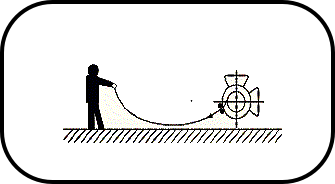
Case 10
Manual Operation
Mounting
Point
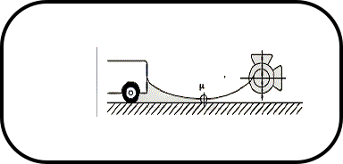
Case 11
Automatic Operation
Mounting
Point
Explanation of the symbols (case f to 7):
Lw= maximum reeling cable length (reeling length for reels traveling in both directions =one-half of the total traveling length h= (installation height) distance between cable deposit plane and drum center [m] LF= cable feeding point i= maximum cable sag (ml in case b and 7 related d to position A in drawing; f1= maximum cable sag [m] related to cable feeding port LF L1= roller or support distance [m]
Calculation formula flfl (m] - l0 x L2 g )
8 X F
L= support distance [m] g= cable weigh [kg/m] F= pulling force [Newton] Explanation of the symbols (case 8 and (()
Lw= maximum reeling cable *gm [m] H8/9= maximum cable length hanging down from the drum [m]
The drum is selected according to the total cable weight of the hanging cable. Additional Weight (E3) must be considered and added to the cable weight
ALFO STD RANGE

Cable Reeling Drums - Spring Driven