

Copyright © All rights reserved. Made By RT World of Business.


|
|
Nominal Torque (kNm) |
Max Torque(KNm) |
Max Speed (1/m in) |
Min Max (Mm) |
DIMENSIONS (mm) |
Mass M |
Moment of Inertia J |
Grease Quantity |
TorsionalStiffnessKx10 | ||||||||
SIZE |
Tk |
Tf |
nk |
d |
D |
C |
A |
Al |
A2 |
E |
f |
G |
H |
[Kg] |
[Kgm2 ] |
[Kg] |
[Nm/rad] |
0 |
1.80 |
4.32 |
6000 |
12-52 |
111 |
43 |
3 |
5 |
7 |
83 |
69 |
39 |
2 |
8 |
0.007 |
0.08 |
4.36 |
1 |
2.76 |
6.62 |
4620 |
18-62 |
142 |
50 |
3 |
8 |
13 |
105 |
85 |
46 |
2 |
13 |
0.018 |
0.09 |
7.31 |
2 |
5.55 |
13.30 |
4140 |
28-78 |
168 |
62 |
3 |
14 |
25 |
131 |
107 |
59 |
2 |
23 |
0.046 |
0.16 |
13.45 |
3 |
8.70 |
20.90 |
4000 |
40-98 |
200 |
76 |
5 |
12 |
19 |
159 |
133 |
69 |
3 |
41 |
0.120 |
0.27 |
24.58 |
4 |
14.10 |
33.80 |
3860 |
50-112 |
225 |
90 |
5 |
24 |
43 |
184 |
152 |
83 |
3 |
60 |
0.229 |
0.47 |
30.34 |
5 |
22.80 |
54.70 |
3720 |
60-132 |
265 |
105 |
6 |
27 |
48 |
212 |
178 |
93 |
3 |
91 |
0.501 |
0.68 |
47.68 |
6 |
34.80 |
83.50 |
3190 |
70-156 |
300 |
120 |
6 |
32 |
58 |
246 |
209 |
106 |
3 |
141 |
1.005 |
0.93 |
68.27 |
7 |
44.00 |
105.60 |
2900 |
85-174 |
330 |
135 |
8 |
37 |
66 |
275 |
234 |
118 |
4 |
199 |
1.734 |
1.54 |
97.85 |
8 |
69.80 |
167.60 |
2570 |
95-190 |
370 |
150 |
8 |
50 |
92 |
307 |
254 |
138 |
4 |
285 |
3.029 |
2.28 |
136.10 |
9 |
83.80 |
201.10 |
2330 |
110-210 |
406 |
175 |
8 |
53 |
98 |
335 |
279 |
154 |
4 |
352 |
4.556 |
3.10 |
159.90 |
10 |
152.00 |
364.80 |
2150 |
120-233 |
438 |
190 |
8 |
58 |
108 |
367 |
305 |
166 |
4 |
428 |
6.165 |
3.90 |
203.30 |
11 |
203.50 |
488.40 |
1800 |
130-280 |
505 |
220 |
10 |
72 |
134 |
423 |
355 |
193 |
5 |
596 |
12.550 |
6.20 |
283.00 |
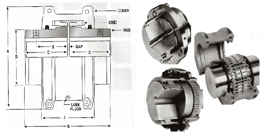
CPLG. |
CPLG. |
MAX |
MIN |
(2) |
(1) |
(1) |
A |
B |
C |
D |
J |
GAP |
S |
SIZE |
RATING |
RPM |
BORE |
MAX |
WT |
WK2 |
|
|
|
|
|
|
|
|
|
Nm |
|
mm |
BORE mm |
kg |
Kgm |
mm |
mm |
mm |
mm |
mm |
mm |
mm |
|
|
|
|
|
|
|
|
|
|
|
|
|
|
|
1020TG |
48 |
4500 |
13 |
27 |
1.80 |
0.0014 |
102.0 |
98.0 |
47.5 |
39.7 |
66.7 |
3.2 |
35 |
1030TG |
136 |
4500 |
13 |
35 |
2.40 |
0.0022 |
111.0 |
98.0 |
47.5 |
49.2 |
68.3 |
3.2 |
40 |
1040TG |
226 |
4500 |
13 |
44 |
3.20 |
0.0330 |
118.0 |
105.0 |
50.8 |
57.2 |
69.9 |
3.2 |
40 |
1050TG |
395 |
4500 |
13 |
51 |
5.20 |
0.0073 |
138.0 |
124.0 |
60.3 |
66.7 |
79.4 |
3.2 |
45 |
1060TG |
621 |
4350 |
19 |
57 |
7.10 |
0.0119 |
151.0 |
130.0 |
63.5 |
76.2 |
92.0 |
3.2 |
53 |
1070TG |
904 |
4125 |
19 |
68 |
10.10 |
0.0185 |
162.0 |
156.0 |
76.2 |
87.3 |
95.3 |
3.2 |
54 |
1080TG |
1864 |
3600 |
25 |
83 |
17.70 |
0.0451 |
194.0 |
181.0 |
88.9 |
104.8 |
115.9 |
3.2 |
65 |
1090TG |
3390 |
3600 |
25 |
95 |
24.50 |
0.0787 |
213.0 |
200.0 |
98.4 |
123.8 |
122.2 |
3.2 |
72 |
1100TG |
5706 |
2440 |
42 |
108 |
41.30 |
0.1782 |
251.0 |
246.0 |
120.6 |
142.1 |
155.6 |
4.8 |
- |
1110TG |
8475 |
2250 |
42 |
117 |
53.60 |
0.2701 |
270.0 |
259.0 |
127.0 |
160.4 |
162.6 |
4.8 |
- |
1120TG |
12428 |
2025 |
60 |
137 |
78.70 |
0.5136 |
308.0 |
305.0 |
149.2 |
179.4 |
192.0 |
6.4 |
- |
1130TG |
18078 |
1800 |
66 |
165 |
118.00 |
0.9885 |
347.0 |
330.0 |
161.9 |
217.5 |
195.2 |
6.4 |
- |
1140TG |
25987 |
1650 |
66 |
184 |
176.00 |
1.8454 |
384.0 |
375.0 |
182.8 |
254.0 |
201.5 |
6.4 |
- |
1150TG |
36130 |
1500 |
108 |
203 |
227.00 |
- |
453.0 |
372.0 |
182.8 |
269.0 |
271.2 |
6.4 |
- |
1160TG |
50810 |
1350 |
120 |
228 |
307.00 |
- |
501.0 |
402.0 |
198.1 |
304.8 |
278.9 |
6.4 |
- |
1170TG |
67740 |
1225 |
133 |
254 |
434.00 |
- |
566.0 |
438.0 |
215.9 |
355.6 |
304.3 |
6.4 |
- |
1180TG |
93930 |
1100 |
152 |
279 |
600.00 |
- |
629.0 |
483.0 |
238.7 |
393.7 |
321.0 |
6.4 |
- |
1190TG |
124000 |
1050 |
- |
335 |
4.40 |
- |
675.6 |
524.2 |
259.1 |
436.9 |
325.1 |
6.0 |
- |
1200TG |
169000 |
900 |
- |
360 |
5.62 |
- |
756.9 |
564.8 |
279.4 |
497.8 |
355.6 |
6.0 |
- |

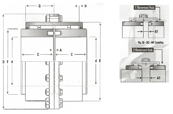
GO _ A , GO-AR & GO-ARR Couplings
DENOMINATION EXAMPLE: GO-A GEAR COUPLING SIZE 6 TAB.11
DOUBLE ENGAGEMENT COUPLINGS FOR HORIZONTAL SHAFTS
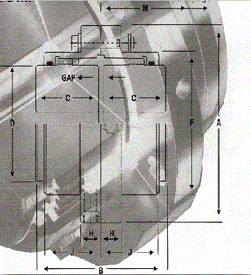

The standard range of gear couplings will accommodate parallel offset, angular misalignment & axial movement, or a combination of all three.
Operating Misalignment | ||
Size |
Parallel |
Angular |
10 |
0.005 |
0.005 |
15 |
0.005 |
0.005 |
20 |
0.010 |
0.010 |
25 |
0.010 |
0.010 |
30 |
0.012 |
0.015 |
35 |
0.012 |
0.015 |
40 |
0.012 |
0.020 |
45 |
0.012 |
0.020 |
50 |
0.012 |
0.020 |
55 |
0.012 |
30.000 |
60 |
0.012 |
0.030 |
70 |
0.012 |
0.030 |
CouplingRating |
MAXSPEEDRPM(1) |
Bore DiaMm(2) |
Dimensions in mm (3) |
|
| |||||||||||
SIZE |
kW/r pm |
kNm |
MAX |
MIN |
A |
B |
(5)C |
D |
F |
H |
J |
M |
GAP |
(6)Masskg |
Mr2InertiaKm2 | |
10 |
0.125 |
1.2 |
8000 |
52 |
16 |
116 |
89 |
43 |
69 |
84 |
14 |
39 |
51 |
3.00 |
4.37 |
0.005 |
15 |
0.261 |
2.5 |
6500 |
65 |
24 |
152 |
102 |
50 |
86 |
105 |
19 |
48 |
61 |
3.00 |
8.96 |
0.019 |
20 |
0.521 |
5.0 |
5600 |
80 |
28 |
178 |
127 |
62 |
105 |
127 |
19 |
60 |
76 |
3.00 |
14.8 |
0.041 |
25 |
0.907 |
8.7 |
5000 |
98 |
35 |
213 |
159 |
77 |
131 |
155 |
22 |
72 |
92 |
5.00 |
26.4 |
0.105 |
30 |
1.344 |
12.9 |
4400 |
115 |
42 |
240 |
187 |
91 |
152 |
181 |
22 |
84 |
106 |
5.00 |
39.6 |
0.195 |
35 |
2.022 |
19,4 |
3900 |
135 |
50 |
279 |
219 |
107 |
178 |
211 |
29 |
98 |
130 |
6 |
65 |
0.454 |
40 |
3.179 |
30.5 |
3600 |
160 |
50 |
316 |
247 |
121 |
210 |
246 |
29 |
111 |
145 |
6.00 |
96.0 |
0.860 |
45 |
4.356 |
41.8 |
3200 |
180 |
55 |
346 |
278 |
135 |
235 |
274 |
29 |
123 |
165 |
8.00 |
131.0 |
1.390 |
50 |
5.940 |
57.0 |
2900 |
195 |
75 |
389 |
314 |
153 |
254 |
306 |
38 |
141 |
183 |
8.00 |
186.0 |
2.530 |
55 |
8.441 |
81.0 |
2650 |
215 |
75 |
425 |
344 |
168 |
279 |
334 |
38 |
158 |
203 |
8.00 |
247.0 |
3,83 |
60 |
9.990 |
95.0 |
2450 |
235 |
80 |
457 |
384 |
188 |
305 |
366 |
26 |
169 |
228 |
8.00 |
299.0 |
5.210 |
70 |
15.310 |
147.0 |
2150 |
280 |
100 |
527 |
451 |
221 |
356 |
425 |
29 |
196 |
266 |
10.00 |
473.0 |
11.000 |
- The maximum speeds specified above are generally based on the limit of the lubricant being used. To attain these speeds a separate balance operation may be necessary depending on the requirements of the application. Special couplings can be supplied for higher speeds or more sensitive applications
- Maximum bores specified are for uniformly loaded drives only.
- All dimensions are subject to confirmation. General arrangement drawings are available which show certified dimensions.
