

Copyright © All rights reserved. Made By RT World of Business.


Example :
Driver : Water Turbine ( 75 Kw at 1500 rpm )
Driven equipment : Screw Compressor
Turbine Bore : 60 mm Compressor Bore : 50 mm
Distance between Shaft Ends : 140 mm
Service Factor for the Water Turbine & Screw Compressor :
Kw/1000 rpm = ( 75 Kw x 1000 x 2 ) /1500
Kw/1000 rpm = 100
Coupling Selection based on max rating : A4B
Coupling Bore Capacity : 75 mm
Maximum Speed for the A4B is 3275 rpm unbalanced
DBSE for the A4B Type SP is 140 mm
The A4B Type is acceptable in this application
- Coupling insert removable without the need to remove either driving or driven equipment.
- Change out of coupling insert is faster than other coupling
- No lubrication or maintenance required over the life of the insert
- The polyutherane insert can be supplied in a variety of hardness to optimise torque capacity and damping.
- Polyutherane is very resistant chemical attack.
- Standard insert can be handle large temperature range iron from -40 o c to 80 o c
- Hubs can be rotated independently during motor test
- No metal – to – metal contact
- Large bore to torque capacity
- Vertical operation possible with standard coupling.
- Retaining rings provided with locking screws as standard.
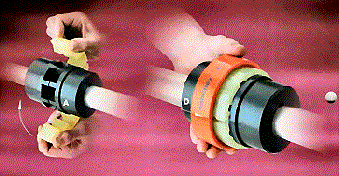
Once hubs (A) and (B) holding ring (D) have been installed and aligned on the shafts the coupling hubs will not have to be moved again during the life of the equipment. The elastic insert (C) can then be installed between the parallel slots formed by the hub teeth.
With the insert position, slide the retaining ring (D) into position over the the polyurethane insert. Centrifugal force will expand the insert under operation ensuring a tight, secure fit inside the retaining ring.
Removing and replacing the coupling insert is very simple and requires no special tools. By removing the retaining ring, the insert can be quickly and easily removed and replaced without the need to undo the screws, bolts or fasteners.
The Samiflex elastic insert is manufactured from a special blend of polyurethane compound manufactured to best meet the demanding characteristics of a high performance elastic coupling.
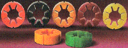
Samiflex elastic inserts are offered in three styles of compound and five hardness ratings allowing the most appropriate insert to be selected for the application.
The standard elastic insert is supplied at 95 shore and is a yellow color. High performance inserts type HD and HDT are colored ochre and red respectively and enable Samiflex torque ratings to be increased by 40% (consult factory).
THE ELASTIC INSERT
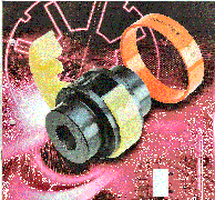
Only four parts to the Samiflex Coupling
The two identical hubs ( items A & B) are manufactured in cast iron, cast steel or aluminium and incorporate four, six or eight teeth, depending on size rating of the coupling.
A precision cast and machined polyurethane insert ( item C ) fits between the hubs and is split axially so fitting and removal can be achieved without removing hubs.
The holding ring, manufactured in steel, polyamide or bronze ( item D) is fitted over the insert securing both insert and ring between hubs. The coupling requires no bolts and nuts.
Samiflex COUPLINGS
The range of Samiflex Couplings has been approved under ATEX directive 94/9EC – for use in potentially explosive atmospheres.

Now there’s a new solution to one of the most costly and troublesome problems facing maintenance personnel - coupling failure and the expensive down time associated with fixing it

Couplings and Fluid Drives
Insert |
Ref |
Hardness |
Colors |
Temp Rating |
|
|
|
80 Shore A |
Clear |
-40°C /80°C |
|
|
|
90 Shore A |
Blue | |
Standard |
STD |
95 Shore A |
Yellow | |
High Temp |
HT |
95 Shore A |
Orange |
-40°C /140 °C |
High Performance |
HD |
97 Shore A |
Ochre |
-40°C /80°C |
HDT |
97 Shore A |
Red |
-40°C /140 °C | |
HR |
65 Shore D |
Green |
-40°C /140 °C |
Coupling Selection
Method
- Application details (for service factor)
- Kilowatt and rpm of the driver
- Shaft details of the driving and driven equipment
- Determine the service factor (SF) from the application and classification lists noted below
- Calculate the maximum Kw/1000 rpm rating:Kw/1000 rpm = (Kw x 1000 x SF ) /rpmSelect the coupling which has a higher max rating
- Compare the maximum rpm capacity & bore requirements to the catalogue limits for the coupling selected
Load Characteristics |
Electric MotorSteam TurbineGlass turbine |
Steam EngineWater Turbine8 Cel. Recip Engine |
6 Cyl. Recip. Engine |
4 Cyl. Recip. Engine |
Constant Torque |
1.0 |
1.5 |
2.0 |
2.5 |
eg.Centrifugal pumps,compressors & blowers, | ||||
light duty agitators and fans | ||||
|
|
|
|
|
|
Slight Fluctuations |
1.5 |
2.0 |
2.5 |
3.0 |
eg. Slurry pumps, Screw compressors, | ||||
Lobe and Vane Blowers. | ||||
|
|
|
|
|
|
Moderate Fluctuations and or |
2.0 |
2.5 |
3.0 |
3.5 |
Slight Shock Loads | ||||
Doubling acting pumps, Rec Comp | ||||
|
|
|
|
|
|
Large Fluctuations and/or |
2.5 |
3.0 |
3.5 |
4.0 |
Moderate Shock Loads | ||||
1 or 2 Cylinder Recip pumps | ||||
|
|
|
|
|
|
Shock loads or |
3.0 |
3.5 |
4.0 |
Consult factory |
Light Torque Reversals | ||||
Slitters, Rod Mill,Hot Mill | ||||
|
|
|
|
|
|
Heavy Shock Loads or |
Consult Factory |
Consult Factory |
Consult Factory |
Consult Factory |
Large Torque ReversalsFeed rolls , Reversing Mills |
(1) Use a minimum Service Factor of 1.25 when driving through a gearbox or using a direct on-line electric motor
(2) Consult Autogard when using a reciprocating engine with fewer than 4-cylinders.
(3) Service Factors are for reference only. Customer experience may dictate the selection of different service factors.