

Copyright © All rights reserved. Made By RT World of Business.


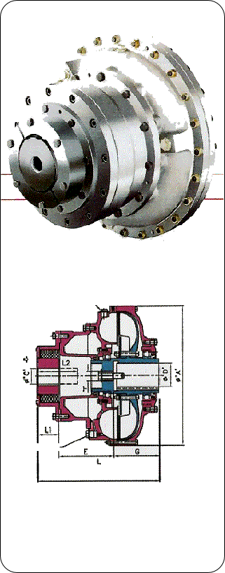
TYPE PSS SIZES 320 TO 1040

The Premium Pembril PSS Fluid Coupling is an advanced design of Constant Fill Fluid Couplings, when used in conjunction with a fixed speed motor, it will give the motor a very light load start, provides smooth acceleration and will ensure overload protection for the motor and driven machine.
Using a Fluid Coupling in the drive line often makes it possible to employ a smaller motor because the Fluid Coupling allows the Motor to run quickly up to speed, where its overload capacity may be used for starting the machine.
Pembril PSS Fluid Couplings are installed between coaxial shafts. Normally PSS Fluid Coupling is mounted between the motor and machine shaft and connected by flexible couplings, which absorb the small assembly misalignments.
During starting condition PSS Fluid Coupling Chamber withdraws almost 30-40% quantity of oil from main circuit to reduce transmitted torque.
After motor reaches the full speed, this retained oil flows back into main circuit, it can be controlled as required by means of nozzles externally.
The PSS Fluid Coupling is a rugged unit. The major components being made from high tensile Aluminium Alloy Casting, it comprises of a basic Fluid Coupling, with the added advantage of Delayed Chamber and Flexible Coupling. Flexible coupling and hollow shaft bore and keyways may be finished to suit the customer requirements.
Filling and Fusible plugs are fitted on the casing wall and the periphery of the coupling.
The main features of Pembril 'PSS' Fluid Coupling are:
- Can be engineered at site to meet the desired acceleration time loll flow rate requirement by replacing the oil filling nozzles without opening the unit.
- Torque transmission by the Fluid Coupling during Motor start - up can be reduced to approximately 50 to 60% of the rated torque.
- Progressively increases the torque applied to the machine,
- Design to achieve good heat-dissipation as compared to other Fluid Couplings
- Hollow Shaft design for compactness
- Manufactured in high tensile aluminum alloy for lighter weight.
- Very high efficiency due to low slip at rated duty.
Selection Data | ||||||
Max. Transmission Capacity in kW at various speeds- RPM | ||||||
size |
720.0 |
870.0 |
960.0 |
1450.0 |
1750.0 |
2950.0 |
320.0 |
4.0 |
7.0 |
10.0 |
34.0 |
56.0 |
85.0 |
370.0 |
5.9 |
11.2 |
15.8 |
56.0 |
100.0 |
140.0 |
410.0 |
10.9 |
19.2 |
26.0 |
89.0 |
140.0 |
275.0 |
450.0 |
16.7 |
29.5 |
39.7 |
134.0 |
185.0 |
450.0 |
500.0 |
30.9 |
55.5 |
74.1 |
175.0 |
275.0 |
|
580.0 |
59.8 |
105.2 |
143.0 |
346.0 |
500.0 |
|
660.0 |
105.3 |
187.0 |
255.0 |
600.0 |
700.0 |
|
740.0 |
199.5 |
337.0 |
388.0 |
783.0 |
|
|
810.0 |
290.0 |
490.0 |
600.0 |
1150.0 |
|
|
910.0 |
532.0 |
760.0 |
860.0 |
|
|
|
1040.0 |
870.0 |
1150.0 |
1252.0 |
|
|
|
ALL DIMENSIONS ARE IN MM
Filling Plug
Control Nozzle

Torque Characteristics During starting
% Speed
Motor Characteristics
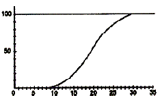
Machine Acceleration
Time seconds
Acceleration Characteristics of Machine

Couplings and Fluid Drives - Soft Start Fluid Drive

OPTIONAL ACCESSORIES
- Fusible Trip device Assembly.
- Brake drum.
- Oversize Half Coupling to accommodate larger shaft dia.
- Solid shaft Couplings can be supplied on request.
TYPICAL APPLICATIONS
Conveyers, Crushers, Ball mills, Ring granulators, Centrifuges, Mixers, Pumps, Frans, etc
CPLG. |
A |
C |
D |
E |
G |
L |
L1 |
L2 |
T |
W |
W1 |
Z1 |
Z2 |
Q |
320.0 |
380.0 |
55.0 |
60.0 |
129.0 |
115.0 |
295.0 |
51.0 |
105.0 |
M30 x 3.5 |
41.0 |
47.5 |
1.7 |
0.4 |
7.2 |
370.0 |
434.0 |
70.0 |
60.0 |
161.5 |
140.0 |
355.5 |
54.0 |
140.0 |
M30 x 3.5 |
63.6 |
73.0 |
3.1 |
0.6 |
10.8 |
410.0 |
454.0 |
75.0 |
80.0 |
186.0 |
155.0 |
401.0 |
60.0 |
160.0 |
M30 x 3.5 |
85.0 |
99.2 |
5.2 |
0.9 |
15.8 |
450.0 |
521.0 |
85.0 |
80.0 |
218.0 |
170.0 |
455.0 |
67.0 |
197.0 |
M30 x 3.5 |
116.0 |
134.5 |
7.4 |
1.8 |
25.0 |
500.0 |
595.0 |
95.0 |
90.0 |
218.0 |
170.0 |
474.0 |
86.0 |
210.0 |
M30 x 3.5 |
145.0 |
172.7 |
13.8 |
2.5 |
30.8 |
580.0 |
660.0 |
115.0 |
110.0 |
258.0 |
176.0 |
529.0 |
95.0 |
243.0 |
M30 x 3.5 |
200.0 |
242.3 |
32.5 |
5.6 |
47 |
660.0 |
749.0 |
115.0 |
110.0 |
320.0 |
180.0 |
595.0 |
95.0 |
285.0 |
M30 x 3.5 |
275.0 |
336.0 |
43.0 |
8.5 |
68.0 |
740.0 |
838.0 |
115.0 |
145.0 |
334.0 |
240.0 |
669.0 |
95.0 |
279.0 |
M30 x 3.5 |
325.0 |
405.1 |
72.0 |
17.9 |
89.0 |
810.0 |
914.0 |
115.0 |
145.0 |
439.0 |
210.0 |
763.0 |
114.0 |
323.0 |
M30 x 3.5 |
330.0 |
438.0 |
112.0 |
27.3 |
120.0 |
910.0 |
1032.0 |
140.0 |
190.0 |
351.0 |
300.0 |
765.0 |
114.0 |
275.0 |
48 X 87 |
740.0 |
878,6 |
215.0 |
38.2 |
154.0 |
1040.0 |
1162.0 |
170.0 |
190.0 |
380.0 |
315.0 |
822.0 |
127.0 |
335.0 |
48 X 87 |
990.0 |
1186.0 |
308.0 |
66.5 |
218.0 |