Copyright © All rights reserved. Made By RT World of Business.


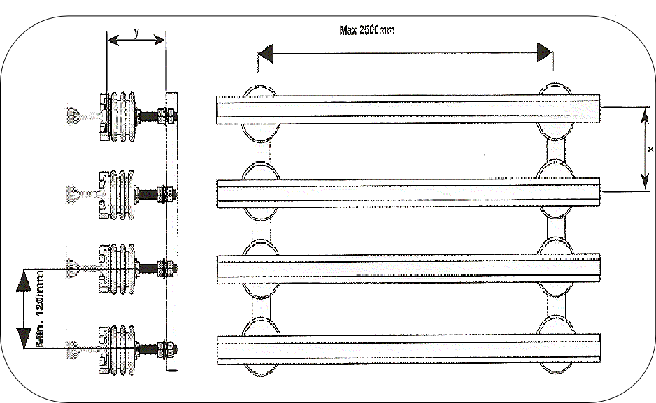
1. Install mounting brackets to I beam or girder, either vertically as Fig. A or horizontally with copper cap facing downwards
Mounting Bracket Spacing: RC20 Rail and high temperature sections 2 meter
RC35 + 45 Rail 2.5 meter Rail Spacing `X': to 550V 150 mm
over 250 mm
Check alignment: 90°to mounting face and parallelity of the bracket spacing.
2. Secure insulators/rail supports to brackets (in accordance with the mounting instructions) leaving bolts hand tight. For general arrangement see Fig A.
When placing the conductors into the insulators, make sure that the bayonet clamp on the insulator does not lock down tight onto the rail. Check the height settings from the mounting bracket to the insulator head rail seat (dimension 'y') are precisely the same throughout the system. The rail must be able to move through the insulator bayonet clamp to allow for expansion and contraction. Check this after tightening down the insulators. The rail must not be restricted at any point otherwise it may buckle when in operation.
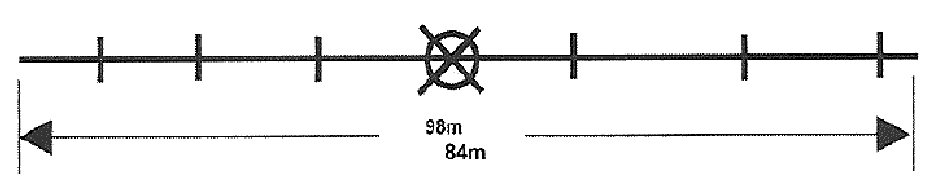
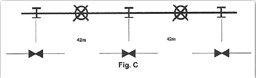
3. Connect the Rails by rigid or expansion joints using the holes provided at the ends of the 7m sections. See Fig. B + C
With longer runs use an expansion joint after every 6 standard lengths of 7 m = 42 m intervals. For special heat environment and strong temperature fluctuations reduce these intervals. Provide an extra insulator/rail support either side of the expansion joint- maximum 250 mm either side
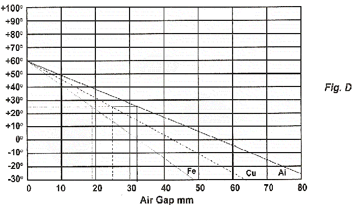
Expansion Gap Calculation
The chart shows orientation lines for the different conductor rails, considering 42m expansion joint intervals. For gap setting move the orientation line in parallel up to the point presenting the anticipated maximum ambient temperature. Then connect point of actual ambient temperature during installation to the right until intersecting with the orientation line. Follow the vertical axis downward to read the air gap dimension in mm.
Example:
Ambient temperature 25°C
Air gap F-rail = 19mm Steel rail with copper cap
Air gap C-rail = 24mm Solid copper rail
4. Anchor rails for controlled directional movement, by fitting two locating clamps around the center insulator of the run or in the center between two expansion joints (see Fig. B + C).
5. Install feeder clamps at feed points. Bolt to web of rail and braze to copperhead.
(For improved conductivity). For short systems center-feed power supply is recommended..