Copyright © All rights reserved. Made By RT World of Business.


Conductor Bar |
Galvanised steel |
Copper |
Aluminium / Stainless steel | |||||
Nominal current |
60A |
100A |
125A |
160A |
250A |
400A |
200A |
315A |
Cross sectional area |
50mm |
63mm |
93mm |
50mm |
63mm |
93mm |
104mm |
120mm |
Maximum system voltage |
|
|
|
|
|
|
|
|
(AC)(contact us for other voltages ) |
1000v |
1000V |
1000v |
1000v |
1000v |
1000v |
1000v |
1000v |
( DC )(contact us for other voltages ) |
1000v |
1000V |
1000v |
1000v |
1000v |
1000v |
1000v |
1000v |
Resistance R (for DC) at20 0 c ohm/m |
0.003584 |
0.002867 |
0.001933 |
0.000342 |
0.000274 |
0.000184 |
0.000301 |
0.000288 |
Impedance Z (for AC) at 20�C ohm./m |
0.003604 |
0.002891 |
0.001968 |
0.000364 |
0.0003 |
0.000221 |
0.000325 |
0.000288 |
Maximum allowable ambient Temperature for 100% duty cycle |
25°C |
25 °C |
25°C |
25°C |
25°C |
25°C |
25°C |
25°C |
Bar length |
4.5m |
4.5m |
4.5m |
4.5m |
4.5m |
4.5m |
4.5m |
4.5m |
Support pitch Standard |
1500mm |
1500mm |
1500mm |
1500mm |
1500mm |
1500mm |
1500mm |
1500mm |
Lateral |
1125mm |
1125mm |
1125mm |
1125mm |
1125mm |
1125mm |
1125mm |
1125mm |
Minimum pitch centres |
|
|
|
|
|
|
|
|
Standard |
43mm |
43mm |
43mm |
43mm |
43mm |
43mm |
43mm |
43mm |
Insulated |
60mm |
60mm |
60mm |
60mm |
60mm |
60mm |
60mm |
60mm |
Expansion sections: not required for runs less than |
150m |
150m |
150m |
150m |
150m |
150m |
150m |
150m |
Minimum bending radius: (horizontal only) |
1.5m |
1.5m |
1.5m |
1.5m |
1.5m |
1.5m |
1.5m |
1.5m |
TECHNICAL DATA | ||||||||
Safe-lee protected conductor bars meet the demands of the following international safety standards. | ||||||||
NFC 20-010, NFC 63-010, NFC 32-070, VIDE 0470, BS EN 60529, DIN 53438. | ||||||||
|
|
|
|
|
|
|
|
|
|
Conductor Bar Cover |
Standard |
Medium Heat |
Maximum allowable temperature in relation to duty cycle | |||||
Material |
PVC |
BAYBLEND | ||||||
Dielectric strength |
180 KV/cm |
240 KV/cm | ||||||
Surface resistivity |
10 (ohm) |
10 ohm | ||||||
Volume resistivity |
10 5215(ohm)/cm |
10 ohm/cm |
Duty cycle |
100 % |
80% |
60% |
40% |
20% |
Vicat softening temperature |
84°C |
120°C |
Maximum allowable ambient temperature with standard insulating cover |
25°C |
30°C |
35°C |
40°C |
55°C |
(Never expose PVC cover |
|
| ||||||
to temperatures in excess |
|
| ||||||
of 80`C) |
|
| ||||||
Flame-test |
54% |
24% | ||||||
Oxygen index |
Self extinguishing |
Self extinguishing | ||||||
Specific density |
1.5 .cm |
1.15 .cm | ||||||
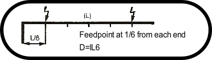

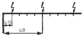
Three feedpoints at L/2 and L/10
From each end
D= L/10
U% = x100%
ohm U = Volt drop in volts
I = Maximum current in Amps
D = Distance between the feed and pick-up points in meters
R = Resistance of conductor in ohms per meter
ohm U = 3 x I x D x Z
ohm U = 2 x I x D x Z
ohm U = 2 x I x D x R

Conductor Rails - Technical Data

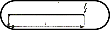
End feed
D=L

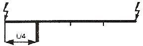
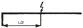
Centre feed
D = L/2

Feedpoint ateach end
D= L/4