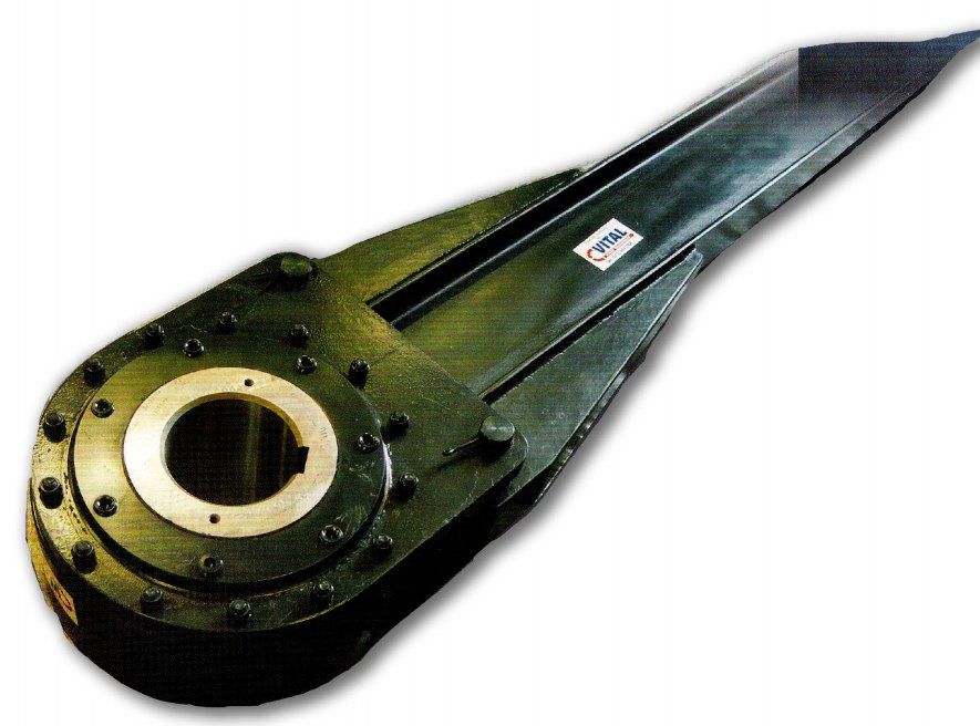
ANTI-RUNBACKS

Dimensions and Data
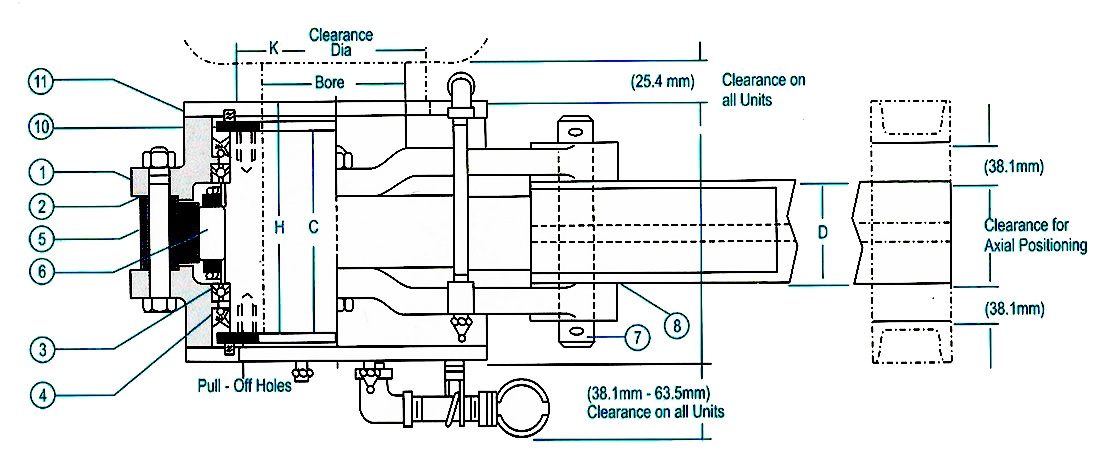
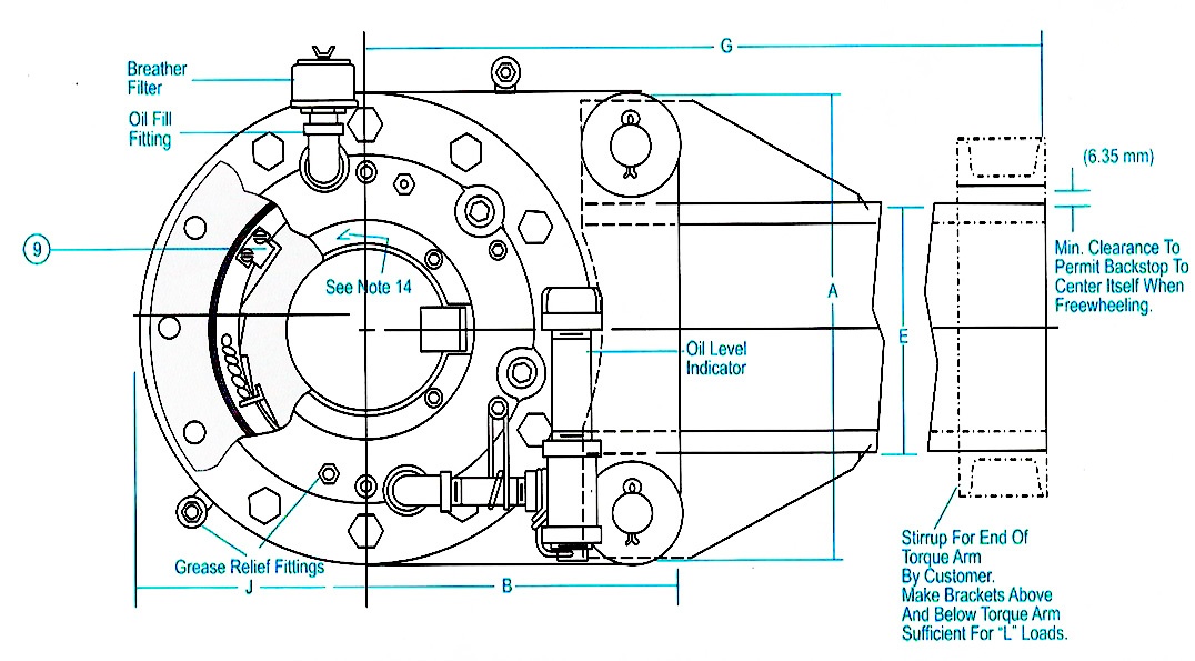
The torque arm end must not be rigidly attached to a steel framework. The bracket or stirrup of the end of the torque arm must provide clearance to permit the Anti Runback to center itself in axial and angular positions to prevent pinching of bearings and damage or failure of the unit and must be sufficient for "L" loads above and below torque arm for Anti Runback size selected. The preferred position is horizontal, to reduce bearing loading for a longer bearing life. Refer to certified drawings and instruction bulletins furnished with each other.
Important notes:
- A Backstop be mounted for desired rotation. Arrow on the inner race indicates the direction of free shaft rotation.
- Before mounting on a shaft, be sure to check the direction of free rotation.
- N Seals are factory packed with grease.
- Before placing it in operation, the backstop must be filled internally with the recommended oil.


1 | COVER PLATE |
2 | GASKET |
3 | BAL BEARING |
4 | OIL SEAL |
5 | OUTER RACE |
6 | SPRAG CAGE |
7 | PIN & COTTER KEYS |
8 | TORQUE ARM |
9 | STOP LUG |
10 | DOUBLELIP SEAL |
11 | OUTER LABYRINTH |
ENGINEERING DATA | |||||||
BACKSTOP SIZE | NOMINAL TORQUE (NM) | MAX TORQUE (NM) | MAX RPM | LOAD "L" (KG) | MAX BORE (mm) | SHIP WEIGHT (KG) | MAX BORE KEYWAY (mm) |
VAR3SC | 3818 | 7637 | 300 | 510 | 75 | 20 x 4.9 | 46 |
VAR6SC | 7600 | 15200 | 250 | 920 | 95 | 25 x 5.4 | 69 |
VAR12SC | 15000 | 30000 | 210 | 1325 | 120 | 32 x 7.4 | 100 |
VAR18SC | 25500 | 51000 | 180 | 1776 | 140 | 36 x 8.4 | 152 |
VAR27SC | 39000 | 78000 | 150 | 2259 | 165 | 40 x 9.4 | 207 |
VAR63SC | 44500 | 89000 | 120 | 4452 | 205 | 50 x 11.4 | 381 |
VAR90SC | 77800 | 155600 | 105 | 6072 | 240 | 56 x 12.4 | 520 |
VAR135SC | 81500 | 163000 | 90 | 8464 | 265 | 63 x 12.4 | 690 |
VAR186SC | 142625 | 285250 | 80 | 10580 | 300 | 70 x 14.4 | 966 |
DIMENSIONS (IN mm) | ||||||||||
BACKSTOP SIZE | A | B | C | D | E | F | G | H | J | K |
VAR3SC | 210 | 143 | 105 | 64 | 76 | 133 | 813 | 119 | 105 | 88 |
VAR6SC | 248 | 165 | 127 | 70 | 102 | 159 | 914 | 143 | 124 | 108 |
VAR12SC | 292 | 203 | 133 | 83 | 127 | 165 | 1270 | 149 | 146 | 133 |
VAR18SC | 343 | 235 | 148 | 92 | 152 | 179 | 1422 | 164 | 168 | 162 |
VAR27SC | 384 | 254 | 178 | 98 | 178 | 213 | 1676 | 195 | 191 | 181 |
VAR63SC | 498 | 311 | 203 | 127 | 254 | 238 | 1981 | 221 | 244 | 241 |
VAR90SC | 584 | 362 | 229 | 140 | 305 | 267 | 2083 | 248 | 270 | 270 |
VAR135SC | 654 | 406 | 254 | 143 | 381 | 298 | 2235 | 276 | 308 | 324 |
VAR180SC | 774 | 419 | 273 | 159 | 457 | 321 | 2388 | 297 | 349 | 362 |
| |
WEEKLY INSPECTION LIST - FOR SLOW SPEED HOLDBACKS | |
Check all pipe work | If leaking - repair |
Check oil level sight glass | If cracked - replace |
Check breather | If elements is blocked - replace. If cover is damaged - replace. |
Check oil level | If low-top up |
Check torque arm pins | If split pins are missing - Fit new split pins |
Check holdback temperature | If more that the ambient temp. Plus 200 degrees call. |
Quesco for assistance (930 C Max with ambient of 520 C) | |
Check vibration sensor | If any vibration other that the installation vibration is present call |
Quesco immediately to assist you. | |
Check The torque arm support stirrup | If loose, or any bolts missing replace or repair immediately, the torque arm side |
clearance must not be less that 25 mm both sides of the torque arm. | |
Check grease in purging cavity | Pump grease in at every inspection, this is only to keep the dust out |
(Remove the dust plug before pumping the grease in) any EP 2 or normal | |
Grease can be used. | |
|
|
3 MONTHLY INSPECTION AND SERVICE |
The inspection must be completed like the weekly inspection and then be serviced as follows |
The holdback oil must be drained and flushed out, preferably whilst unit is operating, to flush properly. |
The holdback must be refilled with an oil viscosity grade of 100. |
The grease dust plug must be removed and all the old grease must be pumped out to remove the dust from the system. |
Do not pump any grease in unless the plugs are removed it will cause holdback failure. |
Oil samples must be analyzed to check for material particles. |
Damaged grease nipples must be replaced |
Damaged pipe leaks must be sealed or replaced. |


